| TECHNICAL DATA |
|---|
| Complete System |
|---|
| Country of Origin | USA |
|---|
| Date Of Introduction | 1970 |
|---|
| Crew | 5 |
|---|
| Caliber | 3.2 in (81 mm) |
|---|
| Weight | 121.5 lb (55.1 kg), including basic issue items |
|---|
| Range | 77 - 5,180 yd (70 - 4,737 m) |
|---|
| Rate of Fire | Maximum: 12 rounds per minute for 2 minutes.
Sustained: 3-5 rounds per minute, indefinitely |
|---|
| M29A1 Cannon |
|---|
| Weight | 28 lb (12.7 kg) |
|---|
| M23A1 Bipod Assembly |
|---|
| Weight | 40 lb (18 kg) |
|---|
| Traverse (approximate) | 95 mils (19 turns), right or left from center |
|---|
| Elevation (approximate) | 800 to 1511 mils (10 mils for each turn of elevation drum) |
|---|
| M3 Baseplate |
|---|
| Weight | 25.4 lb (11.5 kg) |
|---|
| M23A1 Baseplate |
|---|
| Weight | 48 lb (21.8 kg) |
|---|
| M53-Series Sightunit |
|---|
| Weight | 5.25 lb (2.4 kg) |
|---|
| Field of View | 10° |
|---|
| Magnification | 4-power, fixed-focus |
|---|
| Light Source | M53E1 instrument light |
|---|
DESCRIPTION
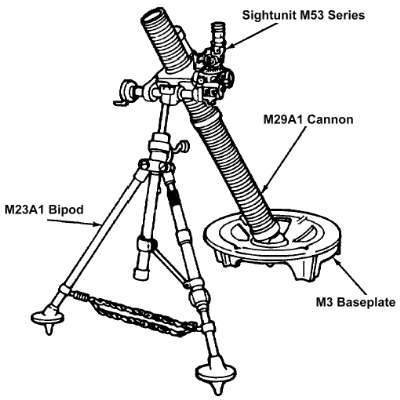
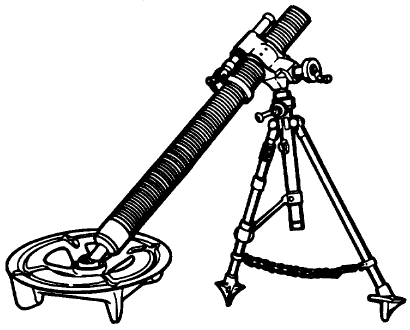
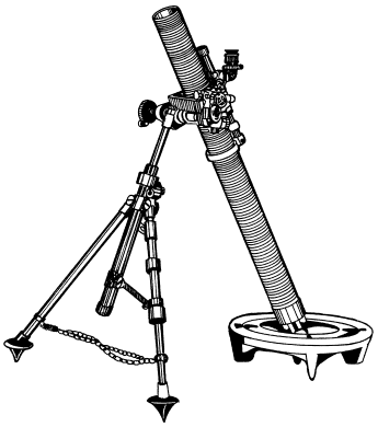
The M29A1 81mm mortar is a smooth-bore, muzzle-loaded, high angle-of-fire weapon. It consists of a cannon assembly, bipod assembly,
and baseplate.
The M29A1 medium mortar offers a compromise between the light and heavy mortars.
Its range and explosive power is greater than the M224, yet it is still light enough to be man-packed over long distances.
The M29A1 weighs about 98 pounds and can be broken down into several smaller loads for easier carrying.
Rounds for this mortar weigh about 15 pounds each.
The M252 replaced the M29A1 in U.S. service.
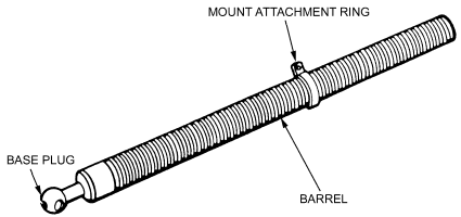
M29A1 Cannon Assembly
The cannon assembly consists of the externally threaded barrel, mount attachment ring, and base plug with a spherical projection that
contains a removable firing pin for drop firing.
M23A1 Bipod Assembly
The bipod assembly consists of the elevating and traversing mechanism, and bipod legs. The bipod absorbs the shock of recoil in firing
with a spring-type shock absorber.
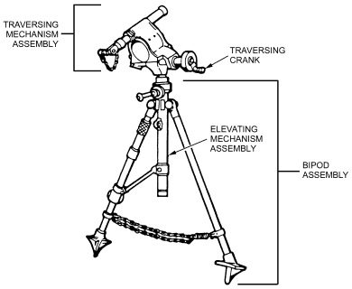
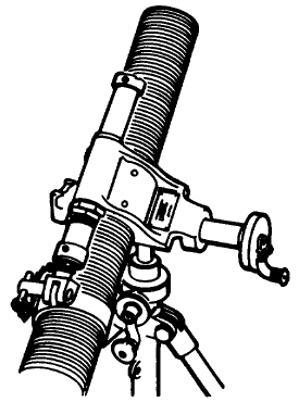
- The bipod legs consist of two tubular steel legs that are hinged at the sides of the elevating mechanisms. The legs have
spiked feet, and their spread is limited by an adjustable chain. A spring attached to the right end of the chain and the right leg
relieves shock to the legs during firing. The right leg has no moving parts. The left leg has a cross-level mechanism consisting of
a sliding bracket mounted on the leg with a locking sleeve and adjusting nut. The sliding bracket is connected to the elevating
housing by a connecting rod. Any movement of the sliding bracket is transmitted through the connecting rod, elevating mechanism
assembly, and traversing mechanism assembly to the barrel, moving it in a like manner. The locking nut locks the sliding bracket in
any desired position on the leg. Cross-leveling is performed to remove any cant from the sight. The sight must be level to attain
true readings in elevation and deflection. Cross-leveling is completed by rotating the adjusting sleeve on the upper part of the leg.
- The elevating mechanism assembly includes a vertical spindle screw moving in an elevating housing assembly. The screw is
turned by a bevel gear and pinion contained in the gear case. The gear and pinion are moved by an elevating crank. The top cover of
the gear case contains an oil fitting for oiling the elevating screw, gear, and pinion.
- The traversing mechanism consists of the yoke assembly, traversing mechanisms, and shock absorber. The yoke body supports
the upper end of the barrel when the mortar is assembled.
- The sightunit is mounted in the dovetail sight slot on the left side of the yoke. The traversing mechanism is an internal screw
shaft operating within a nut and tube. The handwheel turns the screw, which forces the nut to traverse the yoke and, therefore, the
barrel. The tube over the nut is connected to the elevating shaft, which protrudes from the gear case of the bipod. The shock
absorber is a compression spring-type unit mounted in the yoke. A shock absorber clevis screws to the projecting end of the shock
absorber shaft. When the barrel is assembled to the yoke, this clevis is attached to the barrel ring with the shock absorber clevis
locking pin.
BASEPLATES
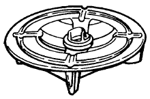
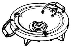
The M3 baseplate is of one-piece aluminum construction, and supports and aligns the mortar for firing. During firing, the base plug on
the barrel is seated and locked to the rotatable socket in the baseplate. The barrel passes through the yoke of the mount and is
secured to the shock absorber by a locking pin.
The M23A1 baseplate is of two-piece steel construction.
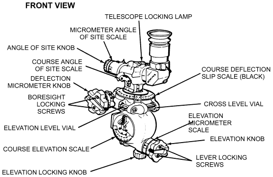
M53-Series Sightunit
The M53-series sightunit, consists of an M128 telescope mount and an M109 elbow telescope fastened together in one unit for operation
The elbow telescope provides magnification and a line of sight from which the weapon is aimed. The telescope mount secures the
telescope in the correct position with respect to weapon azimuth and elevation axis.
The M109 elbow telescope is a lightweight, 4-power, fixed-focus instrument with a 10° field of view that provides the optical
line of sight for aiming the weapon in azimuth and elevation planes.
AMMUNITION
The following are authorized U.S. cartridges for the M29A1 81mm mortar:
- High explosive: M374 series and M362 series.
- White phosphorus: M375 series, M370 series, and M57 series.
- Illuminating: M301 series.
- Training practice: M68 and M880 (SRTR).
The M29A1 may fire M821, M889, and M819 at reduced charges: charge 2 for training and charge 3 for combat.
The following are authorized NATO cartridges for the M29A1:
- United Kingdom (UK): 81mm HE L15A4.
- Canada (CA): 81mm HE L154A4 and M374A2.
- Norway (NO): 81mm ILLUM M301A1 and M301A2.
Click here for more information.
ORGANIZATION
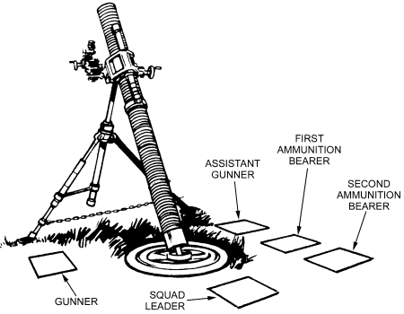
The mortar squad consists of five men. Their firing positions and principal duties are as follows:
- The squad leader stands behind the mortar where he can command and control his squad. In addition to supervising the
emplacement, laying, and firing of the mortar, he supervises all other squad activities.
- The gunner stands on the left side of the mortar where he can manipulate the sight, elevating gear handle, and traversing
assembly wheel. He places firing data on the sight and lays the mortar for deflection and elevation. He and assistant gunner make
large deflection shifts by shifting the bipod assembly.
- The assistant gunner stands on the right of the mortar, facing the barrel and ready to load. In addition to loading, he is
responsible for swabbing the bore after every 10 rounds have been fired or after each fire mission. He assists the gunner in shifting
the mortar when making large deflection changes.
- The first ammunition bearer stands to the right rear of the mortar. He prepares the ammunition and passes it to the
assistant gunner.
- The second ammunition bearer is normally behind the mortar, maintaining the ammunition for firing, providing local
security for the mortar position, filling sandbags, and performing other duties as the squad leader directs. He normally places out
and retrieves the aiming post. The second ammunition bearer is also the squad truck driver. When his duties do not require him to be
with the vehicle, he is used as an ammunition bearer (performing the same duties as the first ammunition bearer).
FIRING
- The mortar is fired by dropping the cartridge down the cannon, base end first.
- The cartridge, falling under its own weight, causes the primer cap to strike the firing pin when bottom of cannon is reached.
- The propelling charge is ignited by the exploding ignition cartridge. Expanding gases force the cartridge from the mortar.
- Fins provide stability in flight for nose impact.
Double loading of mortar ammunition has resulted in catastrophic accidents. Loading a mortar weapon with
two men (alternately) can be very dangerous and could prove fatal. Even with one-man loading, double
loading can occur. This is especially true in rapid fire exercises. For this reason, it is imperative that there be
absolute certainty that the previous round left the mortar tube before a new round is dropped in.
More M29A1 Art
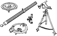
M29A1 major assemblies.
Click on image to see full size: 730x470, 31K, GIF
