| TECHNICAL DATA |
|---|
| | M60 |
|---|
| Country of Origin | USA |
|---|
| Date Of Introduction | 1957 |
|---|
| Crew | 3 (gunner, assistant gunner, ammunition bearer) |
|---|
| Caliber | 0.30 in (7.62 mm) |
|---|
| Cartridge | 7.62mm NATO |
|---|
| System of Operation | Gas |
|---|
| Cooling | Air |
|---|
| Weight, Gun Only | 23 lb (10.4 kg) |
|---|
| Length | 43.5 in (1,105 mm) |
|---|
| Barrel Rifling | R.H., four lands, pitch 1 in 12 inches (305 mm) |
|---|
| Trigger Pull | 6 to 11.5 lb (2.7 to 5.2 kg) |
|---|
| Capacity of Bandoleer | 100 rounds, 7 lb (3.2 kg) |
|---|
| Basic Load | 600-900 rounds |
|---|
| Performance |
|---|
| Rate of Fire | Sustained: 100 rds/min *
Rapid: 200 rds/min **
Cyclic: 550 rds/min *** |
|---|
| Maximum Range | 4,074 yd (3,725 m) |
|---|
| Maximum Effective Range, Tripod and T&E | Area Target: 1,203 yd (1,100 m)
Point Target: 875 yd (800 m) |
|---|
| Maximum Effective Range, Bipod | Area Target: 875 yd (800 m)
Point Target: 656 yd (600 m)
Moving Target: 219 yd (200 m) |
|---|
| M122 Tripod |
|---|
| Weight With T&E Mechanism and Pintle | 16 lb (7.3 kg) |
|---|
| Height of M60 on Tripod | 16.5 in (419 mm) |
|---|
| Notes |
|---|
*Sustained: 6- to 9-round bursts. 4 to 5 seconds between bursts. Barrel changed every 10 minutes.
**Rapid: 10- to 13-round bursts. 2 to 3 seconds between bursts. Barrel changed every 2 minutes.
***Cyclic: Fire continuous burst. Barrel changed every minute.
|
DESCRIPTION
The M60 is general purpose gas-operated, air-cooled, belt-fed, automatic machine gun that fires from the open-bolt position. The
weapon features fixed head space, which permits rapid changing of barrels. It has a maximum rate of fire of 550 rounds per minute.
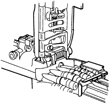
Ammunition is fed into the weapon from a 100-round bandoleer containing a disintegrating metallic split-link belt. It can be fired
from the shoulder, hip, or underarm position; from the bipod-steadied position; or from the tripod-mounted position.
The primary use of the M60 is to support the rifleman in both offense and defense. It provides the heavy volume of close and
continuous fire he needs to accomplish the mission. It can engage targets beyond the capability of individual weapons with
controlled, accurate bursts.
Replaced in U.S. service by the M240B 7.62mm medium machine gun.
M122 TRIPOD
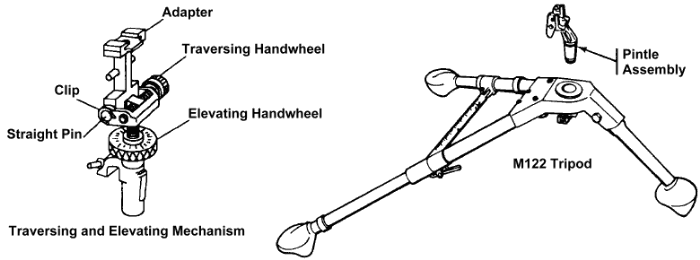
The M122 tripod, traversing and elevating (T&E) mechanism, and pintle provide a stable mount and permit a higher degree of
accuracy and control that is far superior to the bipod.
The tripod may be extended and collapsed without difficulty. It consists of a tripod head, one front leg and two rear legs, and
a traversing bar. The traversing bar connects the two rear legs. It is hinged on one side with a sleeve and sleeve latch on the other,
which allows the tripod to collapse to a closed position for carrying or storage or to lock in an open extended position for use.
The traversing bar also supports the T&E mechanism.
The T&E mechanism provides controlled manipulation and the ability to engage predetermined targets.
The traversing portion of the mechanism consists of the traversing handwheel and traversing slide-lock lever. As the traversing
handwheel is turned, the muzzle of the weapon turns to the left or right, depending on the direction it is turned. The elevating
portion of the mechanism consists only of the elevating handwheel.
The pintle assembly is inserted into the tripod head. The M60's front mounting pin is locked in place on the pintle assembly.
VARIANTS
- M60 (NSN 1005-00-605-7710)
-
1957. "Machine Gun, 7.62-mm, M60". See data above.
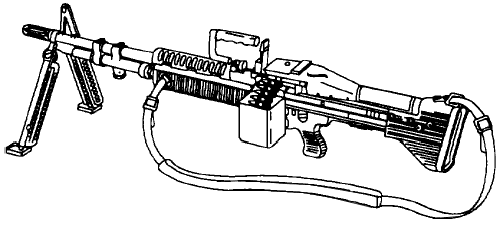
- M60C
-
Electrically controlled aircraft version of the M60.

- M60D (NSN 1005-00-909-3002)
-
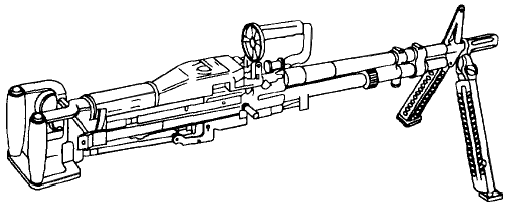
"Machine Gun, 7.62-mm, M60D". The M60D is an aircraft door-mounted or vehicle-mounted machine gun. Has spade grips and an aircraft ring-type sight.
- M60E3
- Lightweight version of the M60.
OPERATION
The M60 machine gun is loaded, fired, unloaded, and cleared from the open-bolt position.
The weapon functions automatically as long as ammunition is fed into it and the trigger is held to the rear. Each time a round is
fired, the parts of the weapon function in a cycle or sequence. Many of the actions occur at the same time. These actions are
separated only for instructional purposes.
The first round of the belt is placed in the tray groove to start the cycle. Then, the trigger is pulled, releasing the sear from
the sear notch. The rear of the sear is lowered and disengaged from the sear notch when the trigger is pulled to the rear. This
procedure allows the operating rod and bolt to be driven forward by the expansion of the operating rod spring. The cycle stops when
the trigger is released and the sear again engages the sear notch on the operating rod.
Cycle of functioning
- Feeding. As the bolt starts its forward movement, the feed cam is forced to the right causing the feed cam lever to
turn in the opposite direction and forcing the belt feed pawl over the next round in the bolt. The next round is then ready to be
placed into the tray groove when the rearward action occurs again. As the bolt moves to the rear after firing, the cam roller
forces the feed cam to the left. The feed cam lever is forced to turn, which moves the feed pawl to the right and places a round in
the tray groove.
- Chambering. As the bolt travels forward, the upper locking lug engages the rim of the round. The pressure of the front
and rear cartridge guides holds the round so that positive contact is made with the upper locking lug of the bolt. The front
cartridge guide prevents forward movement of the link as the round is stripped from the belt. The upper locking lug carries the
round forward. The chambering ramp causes the nose of the round to be cammed downward into the chamber. When the round is fully
seated in the chamber, the extractor snaps over the rim of the round, and the ejector on the rail inside the receiver is depressed.
- Locking. As the round is chambered, the bolt enters the barrel socket. The upper and lower locking lugs contact the bolt
camming surfaces inside the barrel and start turning the bolt clockwise. The action of the operating rod yoke against the bolt
camming slot as the operating rod continues forward turns the bolt, completing its 90° (one-quarter turn) clockwise rotation.
Locking is now complete.
- Firing. After the bolt is fully forward and locked, the operating rod continues to go forward, independent of the bolt,
for a short distance. The yoke, engaged between the firing pin spools, carries the firing pin through the face of the bolt. The
firing pin strikes the primer of the round and the primer fires the round.
- Unlocking. After the round is fired and the bullet passes the gas port, part of the expanding gases go into the gas
regulator through the gas plug. The rapidly expanding gases enter the hollow gas piston, forcing the piston to the rear. As the
operating rod continues to the rear, the operating rod yoke acts against the bolt camming slot. This causes the bolt to begin its
counterclockwise rotation. The upper and lower locking lugs of the bolt contact the bolt camming surfaces inside the barrel socket
and, as the bolt continues toward the rear, it completes a one-quarter turn counterclockwise. The rotation and movement to the rear
unlocks the bolt from the barrel socket. Unlocking begins as the yoke of the operating rod contacts the curve of the bolt camming
slot and ends as the bolt clears the end of the barrel socket.
- Extracting. Extracting begins during the unlocking cycle. The rotation of the bolt loosens the cartridge case in the
chamber. As the piston and bolt move to the rear, the extractor pulls the cartridge case from the chamber.
- Ejecting. As the cartridge case is pulled from the chamber, the bolt passes by the ejector. This procedure causes the
ejector clip to expand, forcing the ejector to push the expended cartridge. The extractor grips the right side of the cartridge and
causes it to spin from the weapon as it reaches the ejection port. The empty belt links are forced out the link ejection port as
the rearward movement of the bolt causes the next round to be positioned in the tray groove.
- Cocking. As the expanding gases force the gas piston to the rear, the operating rod first moves independently of the
bolt. The yoke of the operating rod acts against the rear firing pin spool, pulling the firing pin from the primer of the spent
cartridge case. The action of the piston assembly, continuing to the rear with the firing pin, releases the compression of the
firing pin spring. As long as the trigger is held to the rear, the M60 continues to complete the eight steps of functioning
automatically. When the trigger is released and the sear engages the sear notch, the cycle of functioning is stopped and the weapon
is cocked. To prevent undue wear to the sear and sear notch, the gunner must hold the trigger firmly to the rear during firing.
AMMUNITION
Ammunition is issued in a disintegrating metallic split-linked belt (M13 links). The preferred combat ammunition mix for the
M60 machine gun is four ball (M80) and one tracer (M62).
Click here for more information.
- 7.62mm M80 Ball
- 7.62mm M61 AP
- 7.62mm M62 Tracer
- 7.62mm M63 Dummy
- 7.62mm M82 Blank
- 7.62mm M993 AP
FIRING POSITIONS
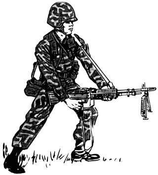
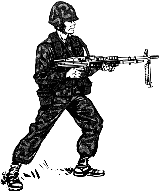
Alternate firing position: Hip
Alternate firing position: Underarm
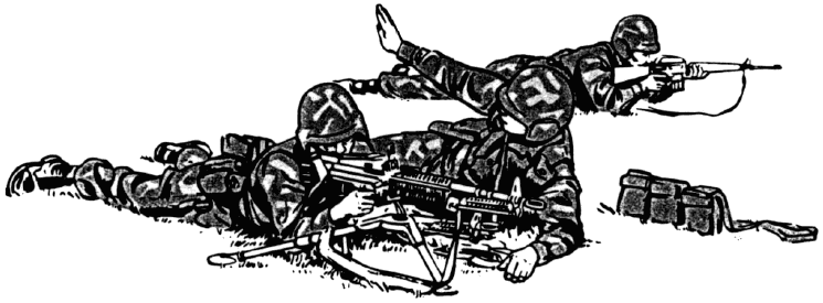
Prone with tripod
WEAPON CAPABILITIES
In the urban environment, the M60 machine gun provides high-volume, long-range, automatic fires for the suppression or destruction of
targets. The M60 machine gun is cumbersome, making it difficult to use inside while clearing a building. However, it is useful outside
to suppress and isolate enemy defenders. The M60 can be fired from either the shoulder or the hip to provide a high volume of assault
and suppressive fires. The use of the long sling to support the weapon and ammunition is preferred.
Because of its reduced penetration power, the M60 machine gun is less effective against masonary targets than a .50-caliber machine
gun. However, the M60's availability and lighter weight makes it well suited to augment heavy machine gun fire or to be used in areas
where .50-caliber machine guns cannot be positioned, or as a substitute when heavy machine guns are not available. The M60 machine
gun can be employed on its tripod to deliver accurate fire along fixed lines and then can quickly be converted to biped fire to cover
alternate fields of fire.
The M60 machine gun can be hard to hold steady to repeatedly hit the same point on a wall. The dust created by the bullet strikes
also makes precise aiming difficult. Firing from a tripod is usually more effective, especially if sandbags are used to
steady the weapon. Short bursts of three to five rounds fired in a U-type pattern are best.
Breaching a brick veneer presents a special problem for the M60 machine gun. Rounds penetrate the cinder block but leave a net-like
structure of unbroken block. Excessive ammunition is required to destroy a net since most rounds only pass through a previously
eroded hole. One or two minutes work with an E-tool, crowbar, or axe can remove this web and allow entry through the breach hole.
More M60 Art
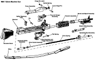
M60 major assemblies.
Click on image to see full size: 900x575, 34K, GIF


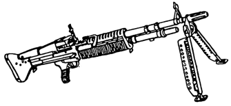
 The M122 tripod, traversing and elevating (T&E) mechanism, and pintle provide a stable mount and permit a higher degree of
accuracy and control that is far superior to the bipod.


 Alternate firing position: Hip
 Alternate firing position: Underarm
 Prone with tripod